Pico <-> Motor Interface
Purpose
C Code had to be written on the Raspberry Pi Pico to interface with the motor controller and interpret the ticks from the encoders.
PID Commands
The Talon SRX expects PID commands with a 1.5ms neutral pulse length, varying up to 2ms for full speed forwards and down to 1ms for full speed backwards. The maximum PWM input frequency is 345Hz. This information is found in the Hardware Manual [1.7MB PDF].
In order to get the Pico to generate these PWM commands, some configuration needed to be done:
// Tell GPIO # They are allocated to the PWM
gpio_set_function(GPIO_Pin, GPIO_FUNC_PWM);
// Find out which PWM slice is connected to GPIO #
uint slice_num = pwm_gpio_to_slice_num(GPIO_Pin);

// Set the clock division with having wrap as max to get 100Hz
pwm_set_clkdiv(slice_num,19.07f);

// Set period of # cycles (0 to cycles inclusive)
pwm_set_wrap(slice_num, cycles);

// Set the PWM running
pwm_set_enabled(slice_num, true);
The clock division was set to have a 100Hz frequency, while the wrap was set to the maximum to get the most precise granularity on the pulse timing.
Since the frequency is 100Hz, the mapping from a floating point duty cycle to a count was very easy:
static inline float map(float value){ // map from -1 - 1 -> 0.1 - 0.2
    return value / 20 + 0.15;
}
The returned number was then multiplied with cycles to generate the correct duty cycle.
This code was tested and the motor was able to move smoothly between full backwards and full forwards.
Encoder
The encoder interface was built up using Programmable I/O, a feature unique to the Raspberry Pi Pico. PIO allows programmable state machines to execute assembly-like code independent of the main processor, avoiding use of interrupts for certain applications. More information is available on page 336-342 of the RP2040 Datasheet [4.9MB PDF]. The quadrature encoders were attached to two PIO state machines, which counted the ticks without the use of the main MCU core.
When the main core needs the count, it can request it by writing a 1 to the RX FIFO of the particular state machine. When the state machine sees this, it makes available the current count in the TX FIFO. The assembly code for the PIOs was taken from example code from the Raspberry Pi Foundation.
Once the code for this scheme was setup correctly, a function was made to get the encoder count as follows:
encoder_t get_encoder_count(side_t side) // Side is LEFT_ENCODER or RIGHT_ENCODER
{
    encoder_t tick_time;
    tick_time.ticks = 0; // defaults to 0 if no response
    tick_time.time = nil_time;
    if (side == LEFT)
    {
        tick_time.ticks = quadrature_encoder_get_count(PIO_LEFT,PIO_SM_LEFT);
        tick_time.time = get_absolute_time();
    }
    else if (side == RIGHT)
    {
        tick_time.ticks = quadrature_encoder_get_count(PIO_RIGHT,PIO_SM_RIGHT);
        tick_time.time = get_absolute_time();
    }
    else
    {
        printf("WARNING: No support for get encoder count for side <%d>",side);
    }

    return tick_time;
}
This system worked, and we were able to get the encoder counts quite easily!
Integration with Communications
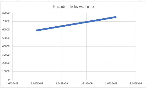
The data and commands were integrated with communications and we were able to retrieve counts from the Pico over SPI, as well as send commands. With a constant speed, the encoder counts looked correct: