Raspberry Pi Pico Bringup
Purpose
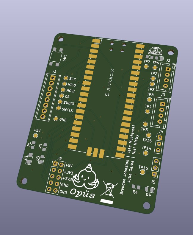
The Raspberry Pi Pico is responsible for reading the encoder values from the motors while providing PWM values to the Talon SRXs. The board has two JST XH connectors to connect to the two encoders, and two three pin headers for PWM output. The board also has some status LEDs, a SPI communication port, a SWD interface for debugging and five general purpose input/outputs for future use.
The following photo is the 3D view from KiCAD of the board.

Soldering
The various components of this board were soldered to facilitate testing. This photo shows the complete product:

Toolchain
Once the board was soldered, the toolchain to work with the Pico was installed. For the most part, setting stuff up for the Pico was a breeze. We just followed the instructions in the Getting Started Guide [33MB PDF] and it worked out of the box for Linux. For Windows, however, some special steps needed to be taken:
- The path length maximum needed to be increased, following directions from Stack Overflow.
- CMake had to be started via the Visual Studio console.
Other than that, the instructions in the Getting Started guide held.