Main Board and Pico Communications
This week we’ve been waiting for our Talon SRX Motor Controllers generously lended from Team 1325. While we wait for them to get here from Mississauga, we decided to get the Pico board in a position where we can plug in the motor controllers as soon as they arrive and begin turning them.
We chose SPI as the communication protocol between the Raspberry Pi Zero control computer and the Raspberry Pi Pico microcontroller because the UART port was left open as a slot for the IMU and I2C doesn’t work particularly well over longer cable runs because of the open-drain drivers. We were thinking that it would be fairly simple to get the two devices talking over SPI because its such a common protocol.
When actually jumping into the code, we discovered that the C++ SDK library functions for the SPI are blocking, which is extremely disadvantageous. This means that execution would be completely paused while sending or receiving bytes. This is a problem in terms of safety because the Pico would not be able to stop the motors if communication was lost in the event of a wire break or Zero crash without the use of the second core or watchdog timer logic.
The packets look like:
#define MAX_PKT_SIZE 10

typedef enum packet_types {
    INIT = 0,
    HEARTBEAT = 1,
    STATE = 2,
    PWM = 3,
    ENC = 4
} opus_packet_type_t;

typedef struct packet {
    uint32_t t_ms; // sequence number, monotonically increasing until wraparound
    opus_packet_type_t type;
    uint8_t len;
    uint8_t data[MAX_PKT_SIZE];
} opus_packet_t;
Attempt 1: Interrupts
The first attempt to solve this problem involved setting up the RXIM interrupt in the Primecell SPI peripheral on the Pico. The overall idea behind this was:
- Processor is doing normal tasks
- Data is sent through the SPI bus to the Pico, which is the slave
- Once the Receive FIFO is more than half full, the SPI peripheral would raise the
RXIMinterrupt, which would be masked to one of the NVIC processor interrupts - An ISR would toggle a flag to indicate data was available
- The main program thread would then read the data from the receive FIFO until it was empty.
This approach proved to be quite problematic because the timing would have to be fairly precise to ensure that the recieve buffer did not fill up. Also, the logic was frustrating to implement. Therefore, we decided to try attempt number two.
Attempt 2: DMA
Direct Memory Access was then attempted. This approach involved setting up the Pico’s DMA controller to transfer data from the SPI peripheral’s recieve buffer to a section in memory directly, without the CPU’s intervention. The overall process flow behind this is:
- Configure DMA to transfer the number of bytes that is required
- Processor does normal tasks
- When DMA has transferred
sizeof(opus_packet_t)bytes, it will raise an interrupt - Processor reads the data, performs the appropriate action, and sends a response back
- Processor clears the interrupt and re-enables DMA, returning to normal tasks
This methodology worked! We were able to transfer packets that were legible from both sides.
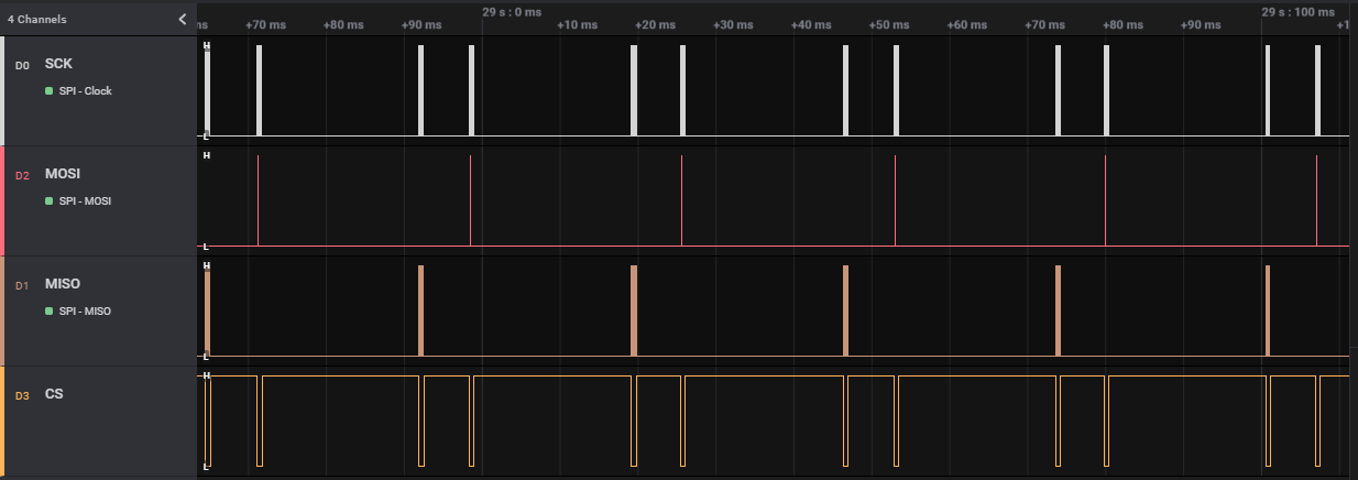
These attempts were recorded with a Saleae Logic Analyzer to debug issues that happened along the way. This is a photo of the communications working properly: